In the realm of precision machining, even minor ambiguities in design can lead to significant quality and functionality risks. This GD&T tip demonstrates how a seemingly straightforward plus/minus tolerancing scheme can mask potential problems, and how a well-implemented profile tolerance, aligned with ISO GPS and ASME GD&T standards, safeguards both product function and manufacturing efficiency.
Original drawing
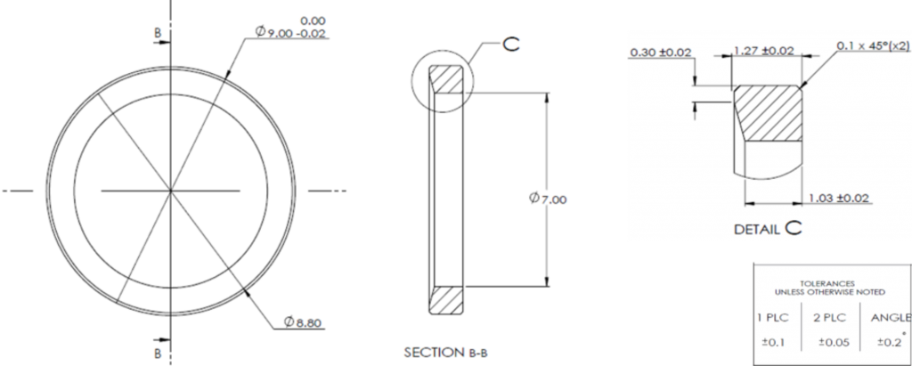
While quoting the following part, we found that the customer drawing is ambiguous and parts produced to specification may not meet the customer’s design intent. Original drawing is seen in figure 1.
Possible interpretation
Since the drawing is a Plus\Minus drawing:
- It is impossible to tell the primary features of the part (what feature dictates the primary directions)
- The conic surface is indirectly toleranced, which may yield to a situation where parts that pass geometric verification may not be functional.
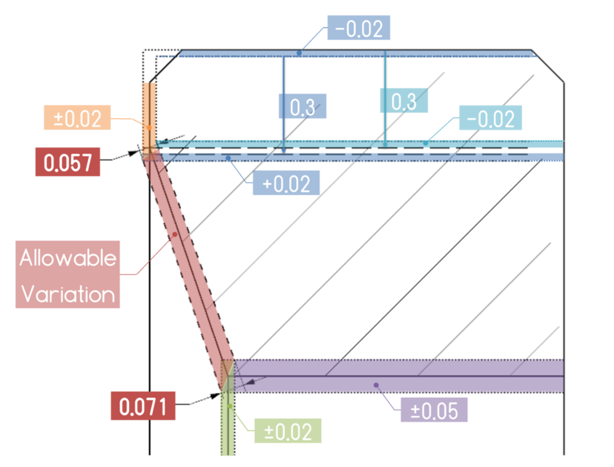
Figure 2 shows a possible interpretation of variation limits. A part that will be within these boundaries will pass geometric inspection, and be at functional risk. the conic taper appears to be a critical feature

Functional constraints
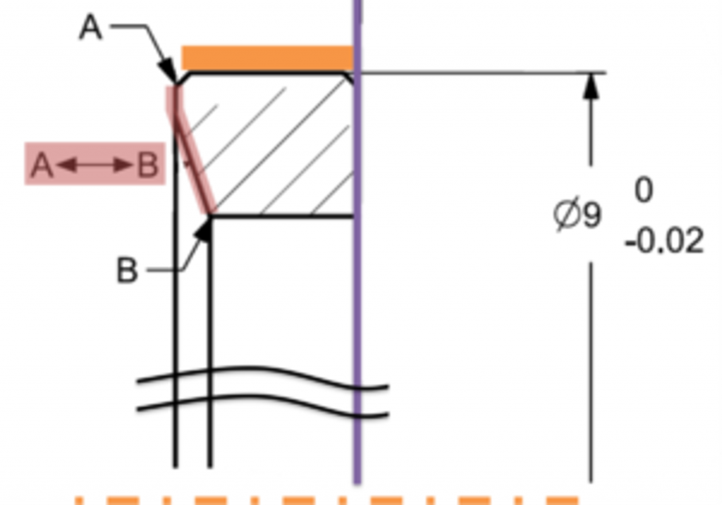
A request for clarification from the customer brought up the functional constraints documented in Figure 3:
- The part lies tangent to an opposite planar surface (marked in purple)
- The part is centered by the outer cylindrical diameter 9 (the axis line of the orange surface)
- Original drawing no direct specification to the conic surface (the area marked in red in Figure 3 between marker A and marker B), the conic and flat are critical features of the part
- The red area should not exceed a symmetrical offset of 0.015mm (In the original drawing, this area could reach the limits of 0.057 – 0.071).
Correct GD&T implementation using profile tolerance
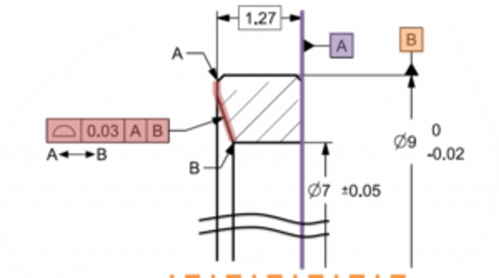
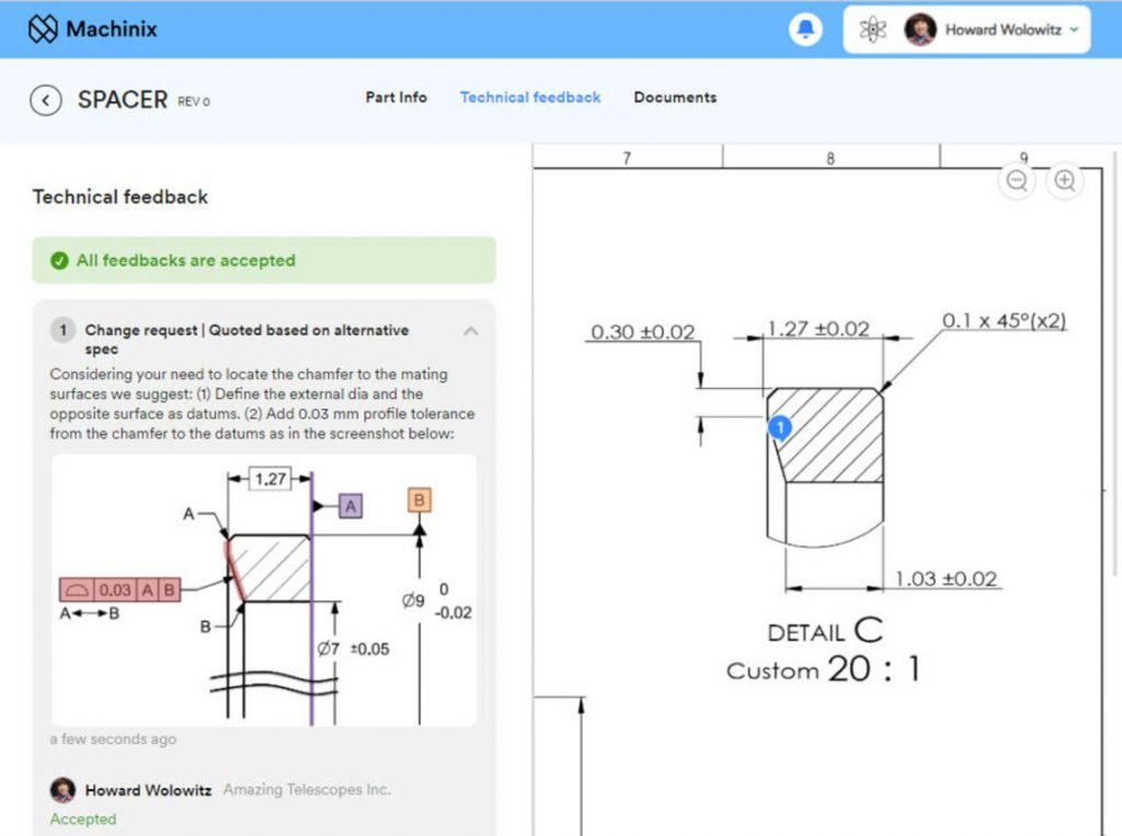
Considering this, Machinx’s recommendation (Figure 4) was to update the drawing,
- Specify purple and orange surfaces as datum features.
- Add direct specification to the critical surface (red) with a profile (instead of plus minus).
(Profile directly specifies a zone that limits size, position, position, and shape variation of the critical features (marked by the red zone in figure 4, and is simpler to control)
A better way to communicate technical feedback
Machinix’s digital platform streamlines the quoting and ordering process of precision machining parts. Using its technical feedback feature it facilitates clear communication between engineers and Machinix technical solutions team. It ensures that any technical issues, including correct implementation of GD&T, are promptly addressed and resolved before production begins. This proactive approach minimizes risks and guarantees a smooth manufacturing experience.
Conclusion
GD&T serves as a critical communication tool in the world of precision parts, seamlessly transferring design intent from the engineer’s mind to the production floor and quality control. By clearly defining tolerances and features, GD&T significantly reduces the risk of quality issues and ensures the part’s functionality.
If you’re looking for expert guidance on implementing GD&T into your precision manufacturing processes – create a quote request and upload your drawings today. Our technical solutions engineers will review and give you valuable feedback within 48 hrs.
The following tip was written in cooperation with TES-TECH. Our technical solution engineers are constantly learning and enriching their knowledge, one way to do that is by attending TES-TEC GD&T technical courses and learn more from Gili Omri and the team.
Recent Comments